Valve Amp
The Fender Champ Amplifier
By Ken Kranz
I have this on the Chava Web site because vacuum tube technology has been a hobby of mine since the 1960's. Obviously modern semiconductors are superior in most respects. It may be of interest to some younger people that missed the tube era to run the simulation and learn something about the technology. Vacuum tubes up to about 1000 watts are normally radiation cooled, the anode that dissipates most of the energy is enclosed inside a glass envelope containing a hard vacuum. Some tube types are designed to run with the anodes glowing red hot, show me a semiconductor that will function at this temperature. Single large water cooled tubes may have outputs and anode dissipations measured in hundreds of kW. At some time I will place a schematic and spice simulation of a power-grid tube project.
Efficiencies are not as bad as many perceive and can exceed 80%. As far as I know all microwave ovens are tube powered using a magnetron's to generate the RF.
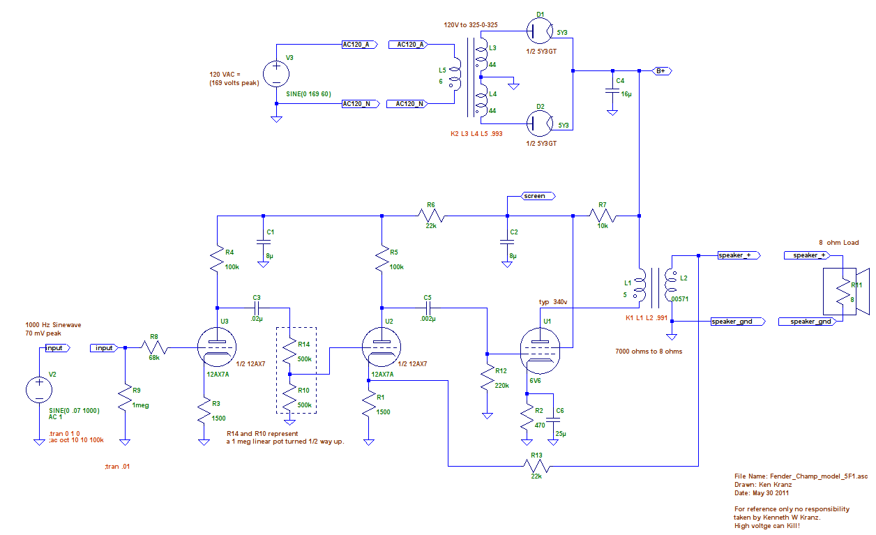
The Fender Champ was introduced in 1948 and produced until 19821. An updated version has been since been produced. It is a favourite with home builders and hobbyists. The sheer simplicity of the design makes it an ideal first tube amplifier project. Power transformers and output transformers are sold by many suppliers at very reasonable prices. Typical price for an output transformer is 15.71€ and for a power transformer 36.13€. Why not build one? You may catch the tube bug. The 5 watt RMS output simple class A amplifier works well and is easily modified for different performance.
The spice simulation has been produced so any potential builder or interested person may experiment with circuit modifications prior to actually implementing them in hardware. The 5 watts output of a single ended tube amplifier sounds much louder than the wattage would suggest. Better spice models for the tubes can be found on the internet, most are copyrighted so are not included. The spice models used are in the .asc file, the symbols are in the zip download, simply run the .asc file from within the unziped folder using LTSpice, it should find the symbols and work ok.
It will be noted the amplifier, as drawn, has some mains hum on the output, simple power supply modification will improve this, remember in 1948 a 16 uF 450 volt capacitor was an expensive item. Simply placing more capacitance on the output of the tube rectifier will damage the rectifier, one option is to fit solid state rectifiers with a series resistor to maintain the original B+ voltage and then fit larger capacitors. A spice model of a 1N4007 diode is included. Just downloaded from the internet are the specifications of a Champ replacement transformer.
- Primary: 117 volt, 60 Hz
- Secondary: 325-0-325 V,
- 375VDC @ 70 mA(DC)
- Filament winding: 6.3 V @ 2 A
- Rectifier Filament: 5 V @ 2 A
I see the Filament winding of 2 A could support a larger output tube, if the tube rectifier was discarded a B+ over 400 could be obtained. A higher power amplifier could be produced. The bias and output transformer would need to be adjusted to suit the new tube and the available power supply. Tubes to try would include the EL34 (pentode) or 6L6GC (beam tetrode) or maybe a KT66. BTW the KT as in KT66 stands for kinkless tetrode. When running the simulation it should be noted that although heater warm up time is not included in the tube models, the screen grid voltage takes a while to stabilise due to the time constant of R7 C2. The inductance of the output transformer was a guess, as are it's coefficient of coupling and DC resistance. This is the link to the zip down load.
References 1 Teagle and Sprung. Fender Amps: The First Fifty Years

Copyright © 2026. Chava Science.